Technomad Flightline Military PA System
Setup and Operation Instructions
Note: this is a setup guide for a Technomad ACC Flightline PA System developed for the Air Force. However, much of the information in this guide applies to Technomad wireless-linked PA systems in general.
Overview You are setting up a Technomad ACC Flightline Military PA system. It is comprised of two Technomad Audio Source Packs, linked to a Technomad Output Pack by microwave Link Kits. You will need these default passwords.
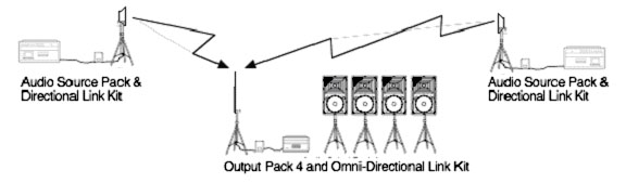
NOTE: Some ACC systems may have an additional Output Pack. This 2nd Output Pack will function just like the first – it receives audio from both Audio Source Packs.
The Audio Source Packs allow an operator to speak into a microphone, play a CD, or play pre-recorded sirens and songs from a Flash RAM playback device. The Link Kits (directional and omnidirectional) convert the audio into IP data, automatically create a “mesh network”, and send the audio as needed from the Audio Source Packs to the Output Pack 4. The Output Pack 4 is a PA system which covers a circular area of approximately 1 mile (1.66 Km) radius under ideal conditions
This system is intended to be quick to setup with no operator experience, to be reliable, simple to use, and to provide unmatched “live” speech clarity, siren playback, and music playback in deployed environments.
Setup
To setup the Flightline PA System you will:
- I: choose locations for the Audio Source Packs
- II: choose a location for the Output Pack 4 PA
- III: attach a directional Link Kit to the Source Packs
- IV: attach an omnidirectional Link Kit to the Output Pack 4 PA.
- V: setup and test the Output Pack 4 PA system
- VI: antennal setup
- VII: test the performance of the complete Flightline Paging System.
Step I: Choose locations for the Audio Source Packs pick the locations where you will locate the Audio Source Packs. Normally, these would be placed at command centers or guard posts.
Step II: Choose locations for the Output Pack 4 PA Pick the locations where you will install the Output Pack 4 PA system. The PA system is comprised of a Control Rack, four Omaha weatherproof military loudspeakers, and four tripods. You should locate the Control Rack (the flight case containing the amplifier, mixer, CD player, etc.) in a weather-protected environment approximately 20 ft. (6M) from where the loudspeakers will be setup. The PA systems should be located in a place that has clear lines-of-sight to the listeners will be. High places (i.e. building roofs, hills, etc) are good locations for the PA system. It is better to choose a location with good line-of-sight to listeners that are a bit farther away than to choose a closer location that would cause the loudspeakers to be “hidden” behind buildings, landscape features, trees, etc. For planning purposes, assume that a .5 mile (.83Km) radius circle around the loudspeaker cluster will have good volume, even if conditions are not ideal (for example, it is windy).
Step III: Attach a directional Link Kit to the Source Packs
The Directional Link Kit consists of two parts: a 1U 19″ rackmount Encoder unit, and a tripod-mounted transmitter/receiver unit. You can identify the Directional Link Kit by its square, aluminum antenna. Note that Technomad has pre-installed the rackmount Encoder unit in the Audio Source Packs. To setup the tripod-mounted transmitter/ receiver, simply:
- unlock / expand / relock the tripod base
- snap the transmitter receiver unit onto the tripod (make sure the two locking pins that stick out of the sides of the tripod base are engaged)
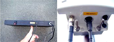
Finally take the provided outdoor Ethernet cable (dark grey, standard Ethernet jack on one end, rotary connector on the other end), and plug it into the standard Ethernet jack on the back of the Encoder unit in the Source Pack. Then take the other end of the cable, and carefully attach it to the jack on the bottom of the white transmitter / receiver unit. Note that you plug the cable into the jack, and then rotate the locking collar to hold it permanently in place.
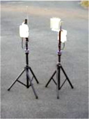
Photo above: Omnidirectional Link Kit (left) and Directional Link Kit (right)
Step IV: Attach an omnidirectional Link Kit to the Output Pack 4 PA.
The Omnidirectional Link Kit consists of two parts: a 1U 19″ rackmount Encoder unit, and a tripod-mounted transmitter/receiver unit. You can identify the Omnidirectional Link Kit by its 3′ long, grey, “stick” antenna. Note that Technomad has pre-installed the rackmount Encoder unit in the Output Pack Control Rack. To setup the tripod-mounted transmitter/ receiver, simply:
- unlock / expand / relock the tripod base
- snap the transmitter receiver unit onto the tripod (make sure the two locking pins that stick out of the sides of the tripod base are engaged)
Finally take the provided outdoor Ethernet cable (dark grey, standard Ethernet jack on one end, rotary connector on the other end), and plug it into the standard Ethernet jack on the back of the Encoder unit in the Output Pack Control Rack. Then take the other end of the cable, and carefully attach it to the jack on the bottom of the white transmitter / receiver unit. Note that you plug the cable into the jack, and then rotate the locking collar to hold it permanently in place.
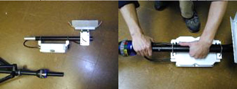
(Photo) Left: Encoder unit, shown out of rack. Note Ethernet cable plugged into jack. Right: Transmitter / Receiver. Note Rotary Ethernet cable attached in the middle.
Step V: Output Pack 4 PA Setup and Testing The Output Pack 4 PA system is comprised of a Control Rack, four Omaha weatherproof military loudspeakers, and four tripods. Transport the PA system to the location you selected above, and then follow the 7 step procedure below to setup the PA:
1. After moving the Control Rack case to the desired location, remove the front and rear lids. Plug the power cord into a good source of grounded AC power – 110V, 10 amps suggested circuit power. The rack is weather-resistant when in transport mode (lids on), but must be protected from water or rain when operating with the lids off.
[Note: the “Sealed Rack Option”, part number 472-tno-895 provides external connectors so you can operate the PA Control Rack in an unprotected area, with the lids attached.]Be sure that the rack is in a sheltered location when deployed! If the amplifier / mixer / other internal components get wet there is a real danger of electrical shock, as with any “indoor use” electrical device. Suggestion: if you are forced to operate the Control Rack in a non-optimal location, you can “hang” the Control Rack lids by just the top two latches, leaving a gap at the bottom edge of the lid where cables can run out.
2. Expand the tripods and put the loudspeakers on them.
3. Arrange the tripods / loudspeakers so one is pointing at each point of the compass (N, S, E, W). The goal is to have four loudspeakers covering a complete circle, with each loudspeaker covering a 90-degree arc:
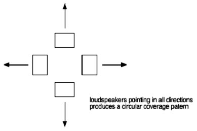
Note: if you are using additional speakers (for example, 6 total), just distribute the 6 speakers to cover 360º evenly.
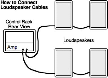
4. Connect two of the loudspeakers to the Control Rack Amplifier using the provided speaker cabling, one speaker connected to the Left output and one speaker connected to the Right output. Any of the four jacks on the loudspeaker can be used. The cable connector should be fully inserted into the loudspeaker jack and then turned clock-wise. You will feel the connector “click” into the proper position when properly seated. To verify proper contact, gently pull on the cable connector- it should not come out of the loudspeaker, nor should it rotate if twisted. If you need to release the cable, pull the small silver locking tab back, then rotate counterclockwise and pull out gently.
Warning: Plugging two cables from the amplifier into the same speaker will cause damage to the system and is not covered by the warranty. The only time more than one cable should be plugged into a loudspeaker is if the second cable is going to another loudspeaker which is not connected to the amplifier in any way.
Connect one of the two remaining “loose” loudspeakers to the loudspeaker connected to Left output of the amplifier, using the provided cable. You can make this daisy-chain connection using any available jacks on the loudspeakers. Finally, daisy-chain the last “loose” loudspeaker to the loudspeaker connected to the Right output of the amplifier. When you are finished you should have two loudspeakers daisy-chained to the Right amplifier output and two daisy-chained to the Left amplifier output as shown here:
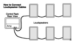
Note: you can “daisy chain” one additional loudspeaker per amplifier, to a maximum of six, like this:
Once you have attached the cables to the loudspeakers, you can crank the tripods up to the desired height. It is strongly recommended that you provide additional stabilization via guy-lines or similar methods if you plan to rise crank the loudspeakers above 6 feet. It is the responsibility of the person performing the setup to ensure that the loudspeaker cluster is stable, and cannot fall over in wind or other disturbance!
5. Turn the two control knobs on the front of the amplifier all the way Clockwise to the ‘0’ position (counter intuitively, this is turning the amp all the way up). On the mixer, turn the Bass and Treble knobs to the “12-noon” position. Turn all the other knobs on the mixer (the knobs with the grey box around them – the volume knobs) fully Counter-Clockwise (this is turning them off).
6. Turn the Master control knob on the mixer up halfway, to the 12-noon position.
7. Now it is time to test the system. Mic test: get a microphone and mic cable from one of the Audio Source Packs (note what jack it was plugged into, so you can reconnect it later). Bring the Mic and cable to the Output Pack 4 Control Rack. Turn the small switch on the body of the mic to OFF. Plug the mic into the Mic 1 input on the back of the mixer. Make sure the Mic 1 volume knob on the Mixer is all the way Counter Clockwise (all the way down). Turn the switch on the microphone to on (forward). Speak into the mic with your mouth TOUCHING THE MICROPHONE GRILL, while SLOWLY turning up the Mic 1 volume knob on the Mixer. DO NOT EXCEED the 12 noon position on the mixer. You will probably hear “feedback” (a high pitched whining) long before you reach the 12 noon position on the Mic 1 volume control – this is normal, and occurs when a microphone is used close to a loudspeaker (especially in front of) a powerful loudspeaker. Try to position the person speaking into the microphone behind the loudspeakers (in the middle of the cluster). This will help reduce feedback. Speaking clearly, and loudly, while keeping your mouth right on the mic grill will also help reduce feedback. Do not point the “ball” of the mic towards any of the loudspeakers.
If you overdrive the amplifier by feeding it too strong a signal from the mixer, you may ‘Clip’ the amplifier. There is a “Clip Light” on the front of the amplifier. It is OK if this blinks occasionally, but if the light is staying on for sustained periods; turns down the Master volume control on the mixer. If the Master Volume is not turned down and clipping continues, the amplifier will shut itself down for @ 5 seconds, then startup again. This will not harm the amplifier, but it is a sign you are driving the amp too hard!
Caution: The best indicator that the system is being improperly operated is distortion. Listen to the system! A common cause of distortion is having the amplifier volume controls turned down and having the mixer master volume and channel volumes (Mic 1, Mic 1, etc.) turned up too far to compensate. Always operate the amplifier with its volume (Gain) knobs turned all the way up, and regulate the overall output of the PA by using the mixer master volume control. If the speakers sound distorted, you should turn down the system immediately and investigate what is causing the distortion. It is possible to damage the speakers even while operating them at less than their rated power if they are not given clean signal from the amplifier.
8. Having tested the Output Pack 4 PA, turn the Mic 1 volume knob on the mixer all the way down. Reconnect the mic to the Audio Source Pack your borrowed it from. On the Output Pack 4 PA mixer, turn the “Control 1” and “Control 2” knobs to the 12-noon position. These knobs set the amount of signal received from Audio Source Pack 1 and Audio Source Pack 2.
Step VI: Antenna Setup
To review, the Output Pack 4 PA system has now have been setup and tested. A directional Link Kit has been connected to the two Audio Source Packs, and an omnidirectional Link Kit has been attached to the Output Pack 4 PA All systems are powered up, and volume settings have been correctly set.
Make sure that the Directional Link Kit antennas can “see” the Omnidirectional Link Kit antenna. The antennas must have a clear line-of-sight, unblocked by trees, buildings, or other obstacles. Position the tripods with the transmitter/receivers on them as needed to get a clear path between the antennas. If possible, mount the antennas 10-15′ above the ground or higher. Note that the directional antennas have a 27-degree coverage angle (both vertical and horizontal). Maximum range is @ 5 miles under ideal conditions.
Step VII: Test the Flightline Paging / Warning System
With the antennas properly oriented and all systems powered up any audio generated by the Audio Source Packs is transmitted instantly to the Output Pack 4 PA, which amplifies the signal and projects it in a circle up to 1 mile in radius. To test, play a CD on one of the Audio Source Packs (remember, set the Master volume of the Mixer to 12-noon, and slowly turn up the CD volume on the mixer). You should hear the CD playing through the Output Pack 4 PA. If the Microphone is used at one of the Audio Source Packs, the Output Pack 4 PA system will generate the same speech, “live”. Likewise, if the Warning Tone Generator is used at one of the Audio Source Packs, the Output Pack 4 PA system will play the same warning tones.
General Notes:
The warning tone generator is simple to use. Select the type of tone desired using the rotary knob, and active the tone generator using the switch. The volume of the warning tone signal is set using its volume knob on the mixer.
Wireless System Frequency / Certifications: 2.4 GHz Microwave, FCC Identifier KINSL9200
WE ARE HERE TO HELP If you have questions, need spare parts, want technical advice, or require any other support please contact Technomad. We are located in Massachusetts, USA (US East Coast Time, GMT – 6 Hours). The phones are typically staffed 10AM-6PM.
Direct-dial number: 617.275.8898. Fax number: 617 424 8233. Email: [email protected] Website: https://bigislanddev.lm.solar Web-form to submit requests: https://bigislanddev.lm.solar/quickresponse/ (in case your email cannot connect to non-secure / commercial systems)